Vulkan Tutorial (30) - Texture mapping - Combined image sampler
소개
튜토리얼의 uniform buffer 파트부터 처음으로 descriptor에 대해 봤습니다. 이 챕터에서는 새로운 타입의 descriptor를 보겠습니다:결합된 이미지 샘플러(combined image sampler) 입니다. 이 descriptor는 셰이더가 이전 챕터에서 만든 것과 같이 같은 샘플러 객체를 통해 이미지 리소스에 엑세스할 수 있도록 해줍니다.
이러한 결합된 이미지 샘플러 descriptor를 포함하도록 descriptor layout, descriptor pool, descriptor set를 수정하는 것으로 시작하겠습니다. 그 다음, 정점에 텍스쳐 좌표를 추가하고 정점 색상을 보간하는 대신, 텍스쳐에서 색상을 읽도록 조각 셰이더를 수정합니다.
descriptor 갱신
createDescriptorSetLayout 함수로 이동해서 결합된 이미지 샘플러 descriptor에 대해 VkDescriptorSetLayoutBinding에 추가합니다. 우리는 그것을 다음에 uniform buffer 바인딩에 넣을 것입니다.
VkDescriptorSetLayoutBinding samplerLayoutBinding{};
samplerLayoutBinding.binding = 1;
samplerLayoutBinding.descriptorCount = 1;
samplerLayoutBinding.descriptorType = VK_DESCRIPTOR_TYPE_COMBINED_IMAGE_SAMPLER;
samplerLayoutBinding.pImmutableSamplers = nullptr;
samplerLayoutBinding.stageFlags = VK_SHADER_STAGE_FRAGMENT_BIT;

std::array<VkDescriptorSetLayoutBinding, 2> bindings = {uboLayoutBinding, samplerLayoutBinding};
VkDescriptorSetLayoutCreateInfo layoutInfo{};
layoutInfo.sType = VK_STRUCTURE_TYPE_DESCRIPTOR_SET_LAYOUT_CREATE_INFO;
layoutInfo.bindingCount = static_cast<uint32_t>(bindings.size());
layoutInfo.pBindings = bindings.data();
조각 셰이더에서 결합된 이미지 샘플러 descriptor를 사용한다는 것을 stageFlags를 설정하여 나타내야 합니다. 그것은 조각의 색상이 결정되는 곳입니다. 정점 셰이더에서 텍스쳐 샘플링을 사용할 수 있습니다. 예를 들어 높이 맵을 통해 정점 그리드를 동적으로 변형할 수 있습니다.
또한 VK_DESCRIPTOR_TYPE_COMBINED_IMAEGE_SAMPLER 타입의 다른 VkPoolSize를 VkDescriptorPoolCreateInfo에 추가하여 결합된 이미지 샘플러 할당을 위한 공간을 만들 것이고, 이를 위해 더 큰 descriptor pool을 만들어야 합니다. createDescriptorPool 함수로 이동해서 이 descriptor에 대한 VkDescriptorPoolSize를 포함하도록 수정합니다.
std::array<VkDescriptorPoolSize, 2> poolSizes{};
poolSizes[0].type = VK_DESCRIPTOR_TYPE_UNIFORM_BUFFER;
poolSizes[0].descriptorCount = static_cast<uint32_t>(MAX_FRAMES_IN_FLIGHT);
poolSizes[1].type = VK_DESCRIPTOR_TYPE_COMBINED_IMAGE_SAMPLER;
poolSizes[1].descriptorCount = static_cast<uint32_t>(MAX_FRAMES_IN_FLIGHT);

VkDescriptorPoolCreateInfo poolInfo{};
poolInfo.sType = VK_STRUCTURE_TYPE_DESCRIPTOR_POOL_CREATE_INFO;
poolInfo.poolSizeCount = static_cast<uint32_t>(poolSizes.size());
poolInfo.pPoolSizes = poolSizes.data();
poolInfo.maxSets = static_cast<uint32_t>(MAX_FRAMES_IN_FLIGHT);
부적절한 descriptor pool은 유효성 검사 레이어가 탐지하지 못하는 문제의 좋은 사례입니다: Vulkan 1.1 부터는 풀이 충분히 크지 않으면 vkAllocateDescriptorSets가 VK_ERROR_POOL_OUT_OF_MEMORY 에러를 내며 실패할 수 있지만, 드라이버가 내부적으로 문제를 해결할 수도 있습니다. 이것은 때때로 (하드웨어, 풀 크기와 할당 크기에 따라) 드라이버가 descriptor pool의 한계를 초과하는 할당으로 벗어날 수 있다는 것을 의미합니다. 다른 경우에는 vkAllocateDescriptorSets가 실패하고 VK_ERROR_POOL_OUT_OF_MEMORY를 반환합니다. 할당이 일부 시스템에서는 성공하지만, 다른 시스템에서는 실패한다면 실망스러울 수 있습니다.
Vulkan은 할당에 대한 책임을 드라이버로 전가하므로 더 이상 descriptor pool 생성을 위해 해당 descriptorCount 멤버가 지정한 특정 타입 (VK_DESCRIPTOR_TYPE_COMBINED_IMAGE_SAMPLER 등)의 descriptor 수만큼 할당해야 하는 엄격한 요구사항이 아닙니다. 하지만 그렇게 하는 것이 모범 사례로 있으며, 향후 모범 사례 유효성 검사를 활성화 하면 VK_LAYER_KHRONOS_validation에서 이러한 유형의 문제에 대해 경고할 것입니다.
마지막 단계는 실제 이미지와 샘플러 리소스를 descriptor set의 descriptor에 바인딩하는 것입니다. createDescriptorSets 함수로 이동합니다.
for (size_t i = 0; i < MAX_FRAMES_IN_FLIGHT; i++) {
    VkDescriptorBufferInfo bufferInfo{};
    bufferInfo.buffer = uniformBuffers[i];
    bufferInfo.offset = 0;
    bufferInfo.range = sizeof(UniformBufferObject);

    VkDescriptorImageInfo imageInfo{};
    imageInfo.imageLayout = VK_IMAGE_LAYOUT_SHADER_READ_ONLY_OPTIMAL;
    imageInfo.imageView = textureImageView;
    imageInfo.sampler = textureSampler;

    ...
}
결합된 이미지 샘플러 구조체에 대한 리소스는 VkDescriptorBufferInfo 구조체에 uniform buffer descriptor의 버퍼 리소스가 지정되는 것과 같이, VkDescriptorImageInfo 구조체에 지정되어야 합니다. 이전 챕터의 객체가 다 모이는 곳입니다.
std::array<VkWriteDescriptorSet, 2> descriptorWrites{};

descriptorWrites[0].sType = VK_STRUCTURE_TYPE_WRITE_DESCRIPTOR_SET;
descriptorWrites[0].dstSet = descriptorSets[i];
descriptorWrites[0].dstBinding = 0;
descriptorWrites[0].dstArrayElement = 0;
descriptorWrites[0].descriptorType = VK_DESCRIPTOR_TYPE_UNIFORM_BUFFER;
descriptorWrites[0].descriptorCount = 1;
descriptorWrites[0].pBufferInfo = &bufferInfo;

descriptorWrites[1].sType = VK_STRUCTURE_TYPE_WRITE_DESCRIPTOR_SET;
descriptorWrites[1].dstSet = descriptorSets[i];
descriptorWrites[1].dstBinding = 1;
descriptorWrites[1].dstArrayElement = 0;
descriptorWrites[1].descriptorType = VK_DESCRIPTOR_TYPE_COMBINED_IMAGE_SAMPLER;
descriptorWrites[1].descriptorCount = 1;
descriptorWrites[1].pImageInfo = &imageInfo;

vkUpdateDescriptorSets(device, static_cast<uint32_t>(descriptorWrites.size()), descriptorWrites.data(), 0, nullptr);
descriptor는 버퍼와 마찬가지로 이 이미지 정보로 업데이트되어야 합니다. 이번에는 pBufferInfo 대신 pImageInfo 배열을 사용합니다. descriptor는 이제 셰이더에서 사용할 준비가 되었습니다!
텍스쳐 좌표 (Texture coordinates)
텍스쳐 매핑을 위한 한가지 중요한 요소가 아직 남아있으며, 이는 각 정점의 실제 좌표입니다. 좌표는 이미지가 실제 지오메트리에 매핑되는 방식을 결정합니다.
struct Vertex {
    glm::vec2 pos;
    glm::vec3 color;
    glm::vec2 texCoord;

    static VkVertexInputBindingDescription getBindingDescription() {
        VkVertexInputBindingDescription bindingDescription{};
        bindingDescription.binding = 0;
        bindingDescription.stride = sizeof(Vertex);
        bindingDescription.inputRate = VK_VERTEX_INPUT_RATE_VERTEX;

        return bindingDescription;
    }

    static std::array<VkVertexInputAttributeDescription, 3> getAttributeDescriptions() {
        std::array<VkVertexInputAttributeDescription, 3> attributeDescriptions{};

        attributeDescriptions[0].binding = 0;
        attributeDescriptions[0].location = 0;
        attributeDescriptions[0].format = VK_FORMAT_R32G32_SFLOAT;
        attributeDescriptions[0].offset = offsetof(Vertex, pos);

        attributeDescriptions[1].binding = 0;
        attributeDescriptions[1].location = 1;
        attributeDescriptions[1].format = VK_FORMAT_R32G32B32_SFLOAT;
        attributeDescriptions[1].offset = offsetof(Vertex, color);

        attributeDescriptions[2].binding = 0;
        attributeDescriptions[2].location = 2;
        attributeDescriptions[2].format = VK_FORMAT_R32G32_SFLOAT;
        attributeDescriptions[2].offset = offsetof(Vertex, texCoord);

        return attributeDescriptions;
    }
};
Vertex 구조체를 수정하여 텍스쳐 좌표를 위한 vec2를 포함하도록 합니다. 정점 셰이더에서 엑세스 텍스쳐 좌표를 입력으로 사용할 수 있도록 VkVertexInputAttributeDescription도 추가해야 합니다. 정사각형 표면을 가로지르는 보간을 위해 조각 셰이더에 전달할 수 있어야 합니다.
const std::vector<Vertex> vertices = {
    {{-0.5f, -0.5f}, {1.0f, 0.0f, 0.0f}, {1.0f, 0.0f}},
    {{0.5f, -0.5f}, {0.0f, 1.0f, 0.0f}, {0.0f, 0.0f}},
    {{0.5f, 0.5f}, {0.0f, 0.0f, 1.0f}, {0.0f, 1.0f}},
    {{-0.5f, 0.5f}, {1.0f, 1.0f, 1.0f}, {1.0f, 1.0f}}
};
이 튜토리얼에서는 왼쪽 상단 모서리 0,0에서 오른쪽 하단 모서리 1,1까지의 좌표를 사용하여 사각형을 텍스쳐로 채울 것입니다. 다양한 좌표로 자유롭게 실험해보세요. 작동 중인 주소 지정 모드를 보려면 0 미만 1 이상의 좌표를 사용해보세요!
셰이더 (Shaders)
마지막 단계는 텍스쳐에서 색상을 샘플링하도록 셰이더를 수정하는 것입니다. 먼저 텍스쳐 좌표를 통해 조각 셰이더로 전달하도록 정점 셰이더를 수정해야 합니다.
layout(location = 0) in vec2 inPosition;
layout(location = 1) in vec3 inColor;
layout(location = 2) in vec2 inTexCoord;

layout(location = 0) out vec3 fragColor;
layout(location = 1) out vec2 fragTexCoord;

void main() {
    gl_Position = ubo.proj * ubo.view * ubo.model * vec4(inPosition, 0.0, 1.0);
    fragColor = inColor;
    fragTexCoord = inTexCoord;
}
정점별 색상과 마찬가지로, fragTexCoord 값은 래스터라이저에 의해 정사각형 영역에 걸쳐 부드럽게 보간됩니다. 조각 셰이더가 텍스쳐 좌표를 색상으로 출력하도록 하여, 이것을 시각화할 수 있습니다.
#version 450

layout(location = 0) in vec3 fragColor;
layout(location = 1) in vec2 fragTexCoord;

layout(location = 0) out vec4 outColor;

void main() {
    outColor = vec4(fragTexCoord, 0.0, 1.0);
}
아래 이미지와 같이 표시되어야 합니다. 셰이더를 다시 컴파일하는 것을 잊지 마세요.
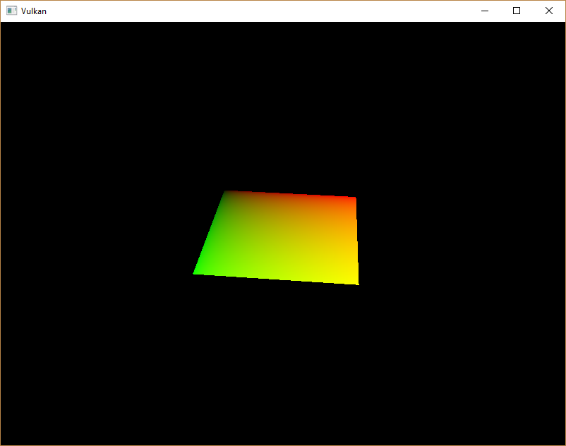
녹색 채널은 수평 좌표를 나타내고 빨간 채널은 수직 좌표를 나타냅니다. 검은색과 노란색 모서리는 텍스쳐 좌표가 정사각형을 가로질러 0,0에서 1,1로 올바르게 보간되었다는 것을 나타냅니다. 색상을 사용하여 데이터를 시각화하는 것은 더 나은 옵션이 없기 때문에, printf로 디버깅하는 것과 같이 동일한 셰이더 프로그래밍입니다.
결합된 이미지 샘플러 descriptor는 GLSL에서 샘플러 유니폼으로 표현됩니다. 조각 셰이더에서 참조를 추가합니다.
layout(binding = 1) uniform sampler2D texSampler;
다른 유형의 이미지에 대해 동등한 sampler1D, sampler3D 유형이 있습니다. 여기에서 올바른 바인딩을 사용 해야 합니다.
void main() {
    outColor = texture(texSampler, fragTexCoord);
}
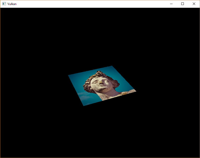
텍스쳐는 내장된 texture 기능을 사용하여 샘플링됩니다. sampler를 사용하고 인수로 조정합니다. 샘플러는 백그라운드에서 필터링 및 변환을 자동으로 처리합니다. 이제 어플리케이션을 실행할 때 사각형에 텍스쳐가 표시되어야 합니다.
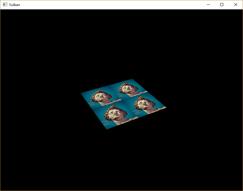
텍스쳐 좌표를 1보다 큰 값으로 바꿔서 주소 지정 모드를 실험해보세요. 예를 들어 다음 조각 셰이더는 VK_SAMPLER_ADDRESS_MODE_REPEAT를 사용할 때 아래 이미지 결과를 생성합니다.
void main() {
    outColor = texture(texSampler, fragTexCoord * 2.0);
}
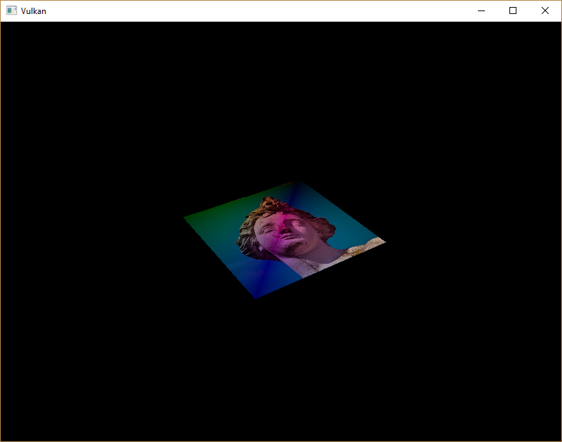
정점 색상을 사용하여 텍스쳐 색상을 조작할 수도 있습니다.
void main() {
    outColor = vec4(fragColor * texture(texSampler, fragTexCoord).rgb, 1.0);
}
알파 채널의 크기를 조정하지 않기 위해 여기서 RGB와 알파채널을 분리했습니다.
이제 셰이더에서 이미지에 접근하는 방법을 알게 되었습니다. 이것은 프레임 버퍼에서도 기록되는 이미지와 결합할 때 매우 강력한 기술입니다. 이러한 이미지를 입력으로 사용하여 3D 세계 내에서 후처리 및 카메라 디스플레이와 같은 멋진 효과를 구현할 수 있습니다.